REMEMBERING THE DISC OXYGENATOR by Kelly D. Hedlund MS, CCP
INTRODUCTION
When I began my career in perfusion 30 years ago, the hard shell disposable bubble oxygenator was king. Membrane oxygenators were certainly available, but only comprised 20% of the market. By the mid-1980’s however, the use of membranes quickly surpassed that of bubblers. Today, membranes are the preferred choice of oxygenation world-wide. Incredibly, bubble oxygenators are still available and used in various parts of the world. In terms of the history of oxygenators, no discussion is complete without mentioning the rotating disc oxygenator (see Figure 1).

Figure 1. Kay Cross disc oxygenator
This “filming” device was first built in 1948 by Viking Bjork whilst working in Clarence Craaford’s lab. Hooker is often mentioned as the originator of the disc oxygenator. In truth, Hooker used a flat disc merely to spread blood centrifugally inside a container. Virtually all of the gas exchange in Hooker’s design occurred on the walls of the device as the blood streamed downward in a filming fashion. Of course, rotating cylinder oxygenators go back to the days of von Frey and Gruber in 1885, as well as to Gibbon’s early attempts at extracorporeal oxygenation in the 1930’s. But it was two ingenious surgeons from Ohio, Drs. Frederick S. Cross and Earl B. Kay (see Figure 2), who brought name-brand recognition to disc oxygenation. Their device, introduced in 1956 as the Kay-Cross Rotating Disc Oxygenator, was soon manufactured by companies like Pemco, Med-Science, American Optical, and Sarns. For a brief time, it was the oxygenator of the day – a truly commercial device to be enjoyed by the masses.
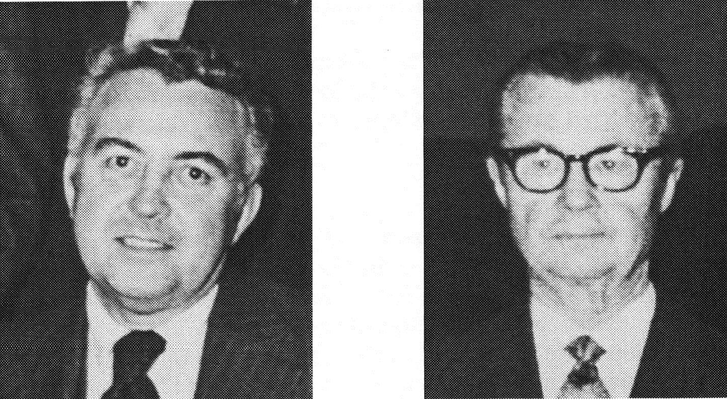
Figure-2.-Dr.Frederick S. Cross (left) and Dr. Earl B. Kay (right)
DISC OXYGENATION
The original Kay-Cross oxygenator contained 59 silicone-coated stainless steel discs mounted on a central shaft separated by stainless steel spacers. The disc assembly was held horizontal within a Pyrex glass cylinder by endplates containing gaskets that sealed the device. Cylinders, approximately 5 inches in diameter, were made available by manufacturers in various lengths (6”, 9”, 13”, 17”, 21”, 25”) to meet the oxygenation needs of the patient. Corrugated discs, which were stamped with 90 degree impressions in a concentric manner, offered 30% more surface area than the conventional flat disc design (see Figure 3).

Figure 3. Flat (left photo) and corrugated (right photo) discs
However, corrugated discs required more spacing between them (4.7 mm instead of 3.6 mm in one commercial model) to avoid “bridging” of blood from one disc to the next. As such, many perfusionists believed the additional space requirement for the entire corrugated disc assembly outweighed the modest advantage of increased filming area. During perfusion, the discs spun at a rate of 120 revolutions per minute. This was generally accomplished by connecting the central shaft to a motor housed inside the heart-lung machine chassis via a flexible cable. Freestanding direct drive motor units were also available. Increasing the spin rate beyond 120 revolutions did not significantly improve gas transfer, and tended to cause splashing and foaming of the blood. Reapplying the silicone coating to the discs, spacers, shaft, and endplates varied greatly between centers (see Figure 4). Kay and Cross advocated re-coating after 20 to 25 pump runs. The lack of an integrated heat exchanger was an obvious drawback of the original rotating disc design. Some centers wrapped a heating wire around the glass cylinder, or employed external heat lamps.
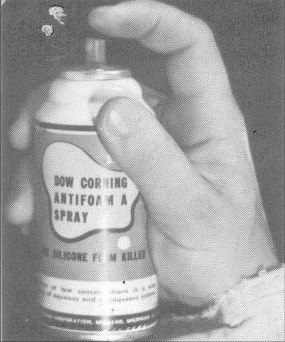
Figure 4. Dow-Corning Antifoam A silicone spray
During his Gibbon Award acceptance speech in 1995, the late Ben Mitchell confessed to using a heating wire as a means to reduce condensation buildup inside the glass cylinder. Unfortunately, both wires and lamps frequently caused clotting at the blood-gas interface as the blood level oscillated up and down the cylinder wall. In response, companies like Olson and Pemco began manufacturing a heat exchanger that fit within the confines of the cylinder directly below the disc assembly (see Figure 5).
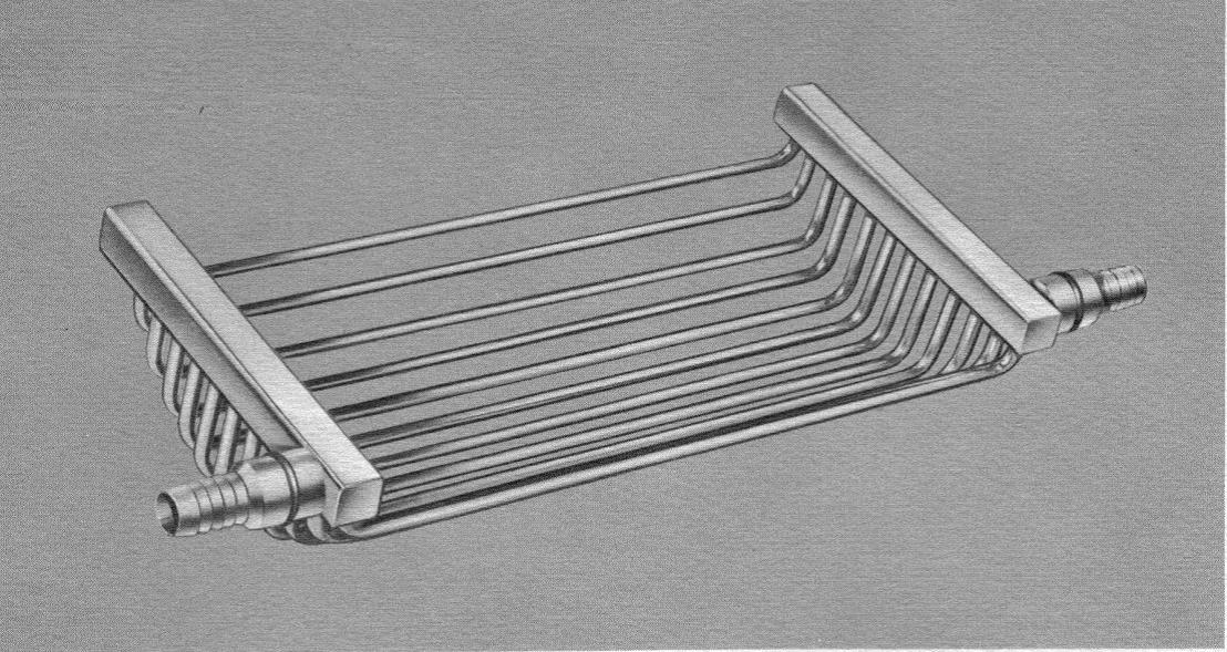
Figure 5. Heat exchanger designed to fit inside the rotating disc oxygenator
A little known fact is that researchers began experimenting with plastic discs as early as 1957. Looking remarkably similar to phonograph records, plastic discs were molded from methylmethacrylate and offered disposability and quick setup (see Figure 6).
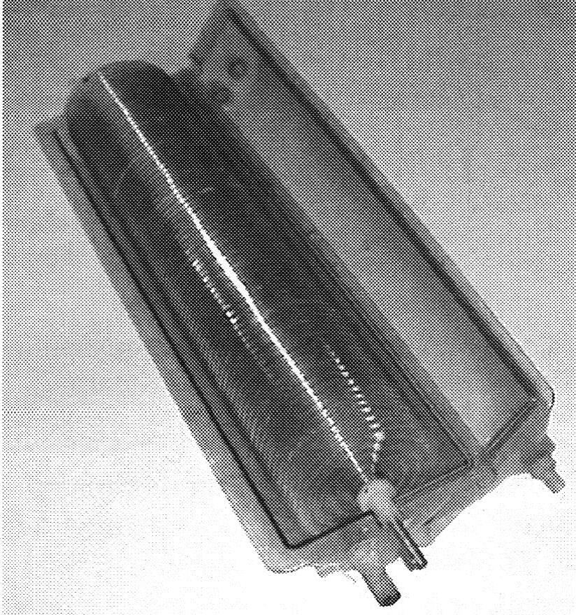
Figure 6. Disposable disc oxygenator made entirely of plastic
In the early 1960s, Sarns devised a rotating disc oxygenator with no endplates. Rather, the shaft and disc assembly were suspended inside a specially contoured metal pan. The lid was made from Lexan – a new plastic at the time that could withstand repeated autoclaving up to 270º F (see Figure 7).
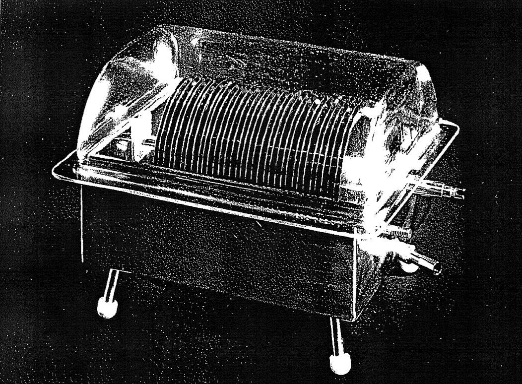
Figure 7. Sarns disc oxygenator with Lexan cover
SUMMARY
Recently, I obtained a rotating disc oxygenator from the Ukraine. It was machined in Kiev in 1959 using the Kay-Cross specifications. According to the perfusionist who sent it to me, it was used on thousands of cases from 1960 until the late 1970s at the Amosov Institute of Cardiovascular Surgery. In 1967, a landmark article published by Gollub, Hirose, and Everett reported that the disc oxygenator (American Optical brand) caused far less destruction of erythrocytes than the bubble oxygenator (Travenol brand) using an in vitro test circuit primed with freshly collected whole human blood. Studies like this are likely the reason why disc oxygenators remained in clinical use for so long, and why Dr. Norman Shumway once proclaimed, “Compared with the rotating disc oxygenator, the bubbler must be considered a second class ticket good only for the short distance, and all too frequently the return trip has been can-celled”. The disc oxygenator’s place in history is secure. For those who haven’t seen one up close, it was truly a feat of engineering – just ask the poor souls who had to clean and assemble it.
ADENDUM BY GARY GRIST RN CCP EMERITUS
One of the things that characterizes the articles in Untold Perfusion History is a personal perspective. Kelly is too young to have ever actually used a disc oxygenator. So with Kelly’s permission I am contributing my own personal perspective on using disc oxygenators.
Most perfusionists have seen the cartoon (see below) showing two perfusionists working at a pump that is exploding and showering them with blood. The cartoon was by a commercial artist named Ron Stetzer, and it was featured in the very first issue of JECT (aka, The Journal of the American Society of Extracorporeal Circulation Technicians) in early 1967. For a brief time, Ron worked at the University of Pittsburgh in the Medical Illustration Department designing charts and graphs for presentation and publication. He no doubt had a connection with somebody who was a perfusionist working with disc oxygenator circuits. The pump depicted in the cartoon is characteristic of the kind used in 1967 along with the clear depiction of a disc oxygenator.
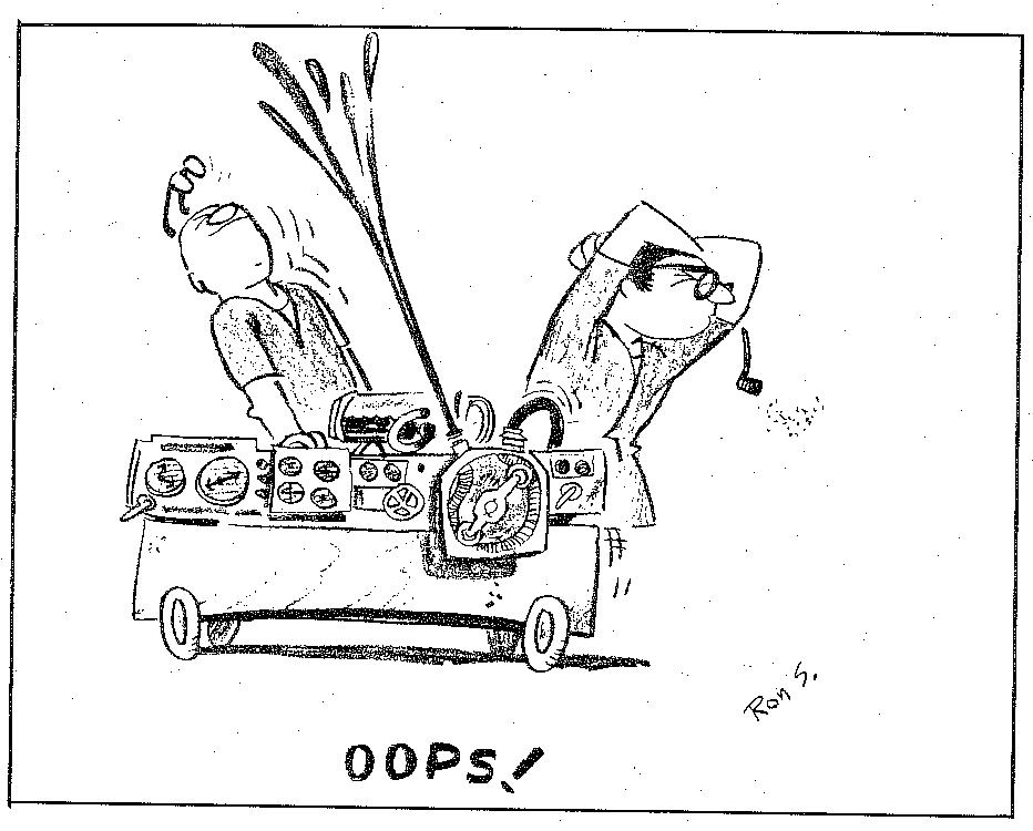
Ron Stetzer “OOPS!” Perfusion Cartoon
The cartoon may be funny to younger perfusionists because it depicts something that rarely happens today, namely, the pump circuitry blowing apart and showering the perfusionists with blood. But I see a deeper meaning in that such accidents were not unusual at a time when disc oxygenator use was common–at least, that was my experience and probably that of others as well, based on the cartoon.
I have another depiction showing a disc oxygenator circuit in use in the 1960s. I have had this photo so long I cannot remember who snapped it (see below). So I apologize for not giving them credit. This photograph is striking in its similarity to Ron’s cartoon: lots of knobs and gadgets on the pump, a disc oxygenator sitting on top of it, and two perfusionists working on it. However, this photo is true to life.
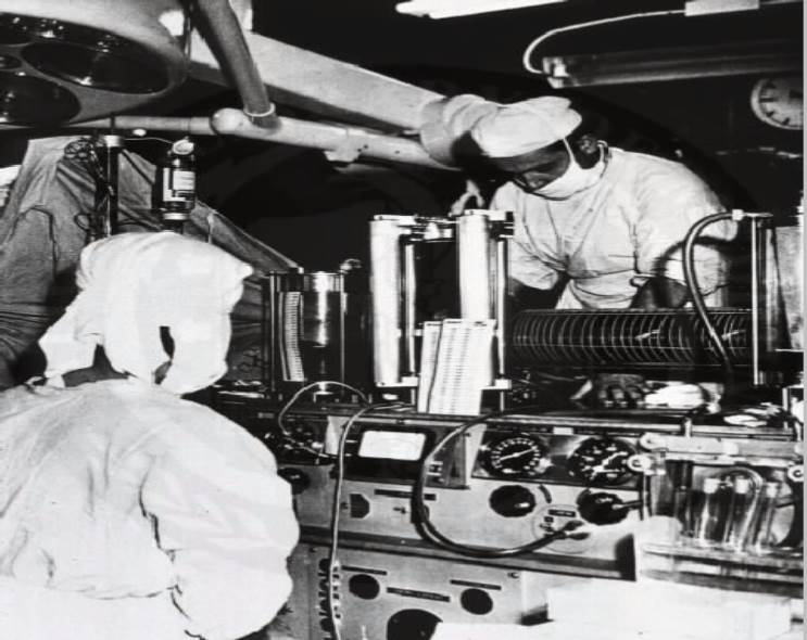
Pump with a disc oxygenator and operators. Photo credit: World Health Organization
http://www.pbs.org/wgbh/nova/body/pioneers-heart-surgery.html
The major components were not disposable and were meant to be reused over and over after laborious cleaning at the end of each clinical case. These circuits (the disc oxygenator, the heat exchanger, the cardiotomy reservoir, and the venous reservoir) were held together with tie rods secured with thumb screws. The screws were tightened against reusable rubber seals that kept the components from leaking. However, getting the multiple tie rods torqued down consistently and tightly enough without cracking the glass cylinders was difficult. Despite our best efforts, the seals often leaked, and it was a major task to control blood leakage during the case. The blood ports and tubing connectors used were mostly stainless steel compression fittings. If the compression ring was too loose, it leaked blood. If the compression ring was too tight, the polyvinyl tubing became distorted and it leaked blood or ran the risk of entraining room air if blood flows were low. The compression ring had to be “just right” or it leaked. As the blood temperature changed, the metal expanded or contracted and what was “just right” five minutes ago became a leak.
The photo shows the back of the primary perfusionist who is turning knobs and running the pump. The second perfusionist who is facing the first is doing the job of controlling the blood leaks. If you look closely you will see that the front right side of his scrub gown has a large blood stain on it. And his left hand, just visible below the disc oxygenator, is holding a large lap sponge that was being using to wipe up blood spillage. So Ron Stetzer’s cartoon is not far from reality in the days when we used disc oxygenators.
I want to thank Kelly for his contribution to the Perfusion Theory web page, the Untold Perfusion History section. And I thank Mark Kurusz for providing the cartoon and editing this addendum.